
 فقط پیامک (09010609492)
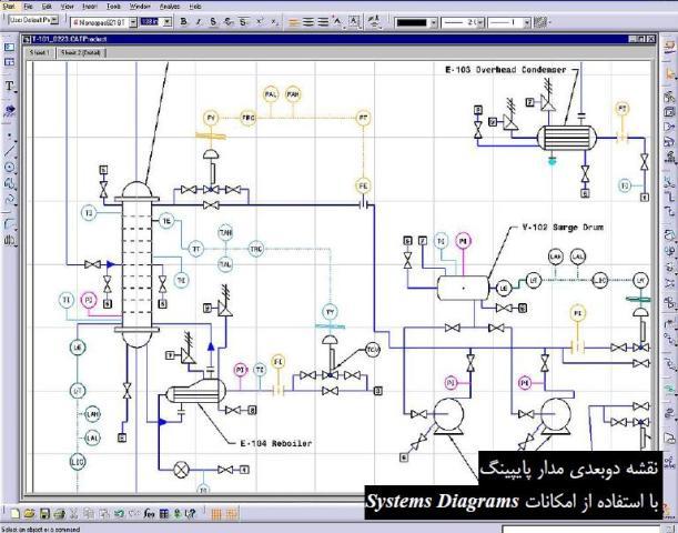
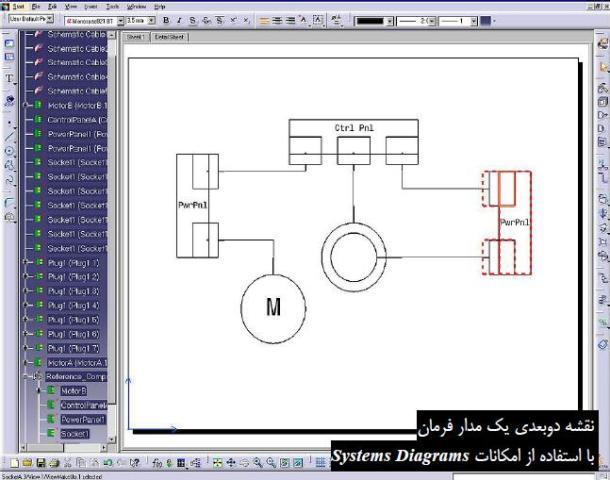
در محیط Piping & Instrumentation Diagrams نرم افزار کتیا، يك محيط كاري پايه براي ساير محيط هاي كاري است كه در آن دياگرام سيستم ها به صورت دوبعدي رسم مي شود. محیط Piping & Instrumentation Diagrams به صورت مستقل نصب نمي شود و از این محیط برای رسم نقشه هاي دوبعدي شبكه لوله استفاده مي شود. تمامي اين دياگرام ها مي توانند با محيط هاي سه بعدي ارتباط برقرار كنند و بعد از رسم نقشه هاي دوبعدي از آنها براي مدل كردن سه بعدي همين سيستم ها استفاده مي شود و ليست قطعات مستقيماً استخراج مي شود . چون هر كدام از اين سيستم ها داراي علائم مخصوص مي باشند، آنها در كاتالوگ هاي ديجيتالي در اختيار كاربر قرار مي گيرند تا او فقط بر طراحي مدار متمركز شود...
| مجوعه آموزشهای نرم افزار پیشرفته CATIA |
| مجموعه آموزشهای مهندسی پایپینگ |
| مجموعه آموزشهای نقشهکشی صنعتی |
راهنمای ترسیم نقشه های دوبعدی شبکه لوله (پایپینگ، Piping) در محیط Piping & Instrumentation Diagrams نرم افزار CATIA، یکی از راهنماهای مرجع و کاربردی در زمینه آموزش ترسیم نقشه های دو بعدی شبکه لوله (پایپینگ) در نرم افزار کتیا می باشد و کلیه دستورات محیط Piping & Instrumentation Diagrams در این راهنما بطور کامل شرح داده شده است. این راهنما (help) مشتمل بر 296 صفحه، به زبان انگلیسی روان، تایپ شده، به همراه تصاویر رنگی، با فرمت PDF، به ترتیب زیر گردآوری شده است:
Getting Started
- Entering the Workbench
- Setting up Working Units and Grid
- Placing Components
- Routing a Piping Line or I & C Loop
- Placing Components in a Piping Line
- Repositioning Components in a Network
- Saving Documents
User Tasks
- Routing Piping Lines and I & C Loops
- Routing Between Equipment
- Creating a Branch
- Moving a Branch
- Manage Piping Lines and I & C Loops
- Creating a Line ID
- Querying a line ID or its members
- Select/Filter Line IDs
- Transfer members of a line ID
- Deleting a line ID
- Renaming a Line ID
- Modifying the Properties of a Line ID
- Merging Line IDs
- Importing Line IDs
- Placing components
- Placing component multiple times
- Placing a nozzle on a component
- Modify object properties
- Edit or Display Properties of an Object
- Filter the Properties of an Object
- Renaming Objects
- Propagate Object Properties
- On and Off Sheet Connectors
- Place On and Off Sheet Connector
- Link/Unlink On and Off Sheet Connectors
- Query Connector for Linked Object
- General Design Modification
- Search for Objects in a Document
- Display Flow Arrows in Document
- Display Line Gaps in Document
- Connect Objects
- Disconnect Objects
- Measure Distance Between Objects
- Move Design Elements
- Align Objects
- Defining Frame Information
- Modifying a Component
- Rotating a Component
- Flipping a Component in Free Space
- Flipping a Connected Component
- Changing the Scale of a Component
- Switch Graphic Representations
- Replacing a Component
- Delete/Unbuild a Component
- Modifying a Route
- Setting Graphic Properties of a Line
- Adjust the Position of a Segment
- Move the Extremity of a Route
- Lock or Unlock a Route
- Breaking a Route
- Connecting Two Routes
- Set the Flow Direction of a Route
- Display Flow Arrows on a Line
- Creating and Managing Zones
- Creating a Zone
- Creating a Boundary
- Modifying a Boundary
- Updating a Boundary
- Querying a Zone
- Modifying the Properties of a Zone
- Delete/Rename a Zone
- Annotating Diagrams
- Creating a Standard Annotation
- Create an Annotation with an Attribute Link
- Editing Annotation on a Placed Component
- Building new components
- Building a Graphic
- Create a Component with Specified Type
- Define Connectors on a Component
- Defining Dynamic Connectors
- Define Flow Path on a Component
- Define Multiple Representations of a Component
- Storing objects in a catalog
- Analyzing Networks
- Analyze Network for Connections
- Viewing Related Objects
- Performing Checks and Applying Design Rules
- Using Knowledgeware Packages
- Importing Checks from Knowledgeware
- Opening a Sample Document
- Checking a Document for Design Errors
- Applying Design Rules to a Document
- Computed Attributes - 2-D
- Title Block and Printing
- Printing a Sheet
- Transferring a Diagram
- Physical Part Selection
- Define the Physical Part Type of a Component
- Select the Physical Part Number of a Component
- Query the Physical Properties of a Component
- Creating Component Groups
- Building a Component Group
- Storing objects in a catalog
- Placing a Component Group
- Views
- Importing Zones from a 3-D Document
- Migrating V4 Models to V5
- Creating a Directory Structure
- Exporting the V4 Project Registration Model
- Exporting the V5 Feature Dictionary
- Comparing the XML Output
- Importing the XML Output
- Exporting V4 Piping Lines
- Migrating the V4 Model
- Connecting Elements
- Managing Publications
- Using ENOVIA
- Creating a Product
- Importing a Product
- Saving a Document in ENOVIA
- Saving a Work Package
Customizing
- Customizing Settings
- Diagrams
- Display
- Design Criteria
- General
- Project Resource Management
- Using the PRM Command
- Understanding Project Resource Management
- Checking a PRM File for Errors
- Feature Dictionary: Creating Object Classes and Attributes
- Defining User Names for Classes & Attributes
- Comparing Feature Dictionaries
- Mapping the Functional Physical Classes
- Opening a Document Without CATfct File
- Creating Custom Reports
- Defining the Report Format
- Generating a Report
- Generating a Report from a Macro
- Creating a Toolbar Shortcut for a Macro
- Defining Options
- Finding Sample Data on Various Platforms
- Specifications Tree
- Object Naming
- Modifying the Object Naming Rules
- Add Computed Attribute to Object Name
- Creating Text Templates
- Creating a Text Template
- Creating a Text Template Catalog
- Placing a Text Template
- Adding Template to Reference Component
- Line ID Catalogs
- Displaying Line ID Properties in Catalog
- Modifying/Updating a Lines Catalog
- Working with ENOVIA
- Setup for Enovia
- Resources That Must be Placed in ENOVIA
Workbench Description
- Design Modify Toolbar
- Build Create Toolbar
- Design Create Toolbar
- On/Off Sheet Connector Toolbar
- Line ID Toolbar
- Zone Toolbar
- Glossary
- Index
توجه: کاربران نگران زبان انگلیسی کتاب نباشند. حتی کاربرانی که سر انگشتی زبان انگلیسی یاد دارند قادر خواهند بود از این کتاب بهره کافی را ببرند. لازم به ذکر است که آموزش ترسیم نقشه های دوبعدی شبکه لوله (پایپینگ، Piping) در محیط Piping & Instrumentation Diagrams نرم افزار CATIA در این کتاب به صورت قدم به قدم (Step to Step) همراه با تصاویر واضح و رنگی می باشد.
جهت دانلود رایگان راهنمای ترسیم نقشه های دوبعدی شبکه لوله در محیط Piping & Instrumentation Diagrams نرم افزار CATIA بر لینک زیر کلیک نمایید:

اگر به فراگیری مباحث مشابه مطلب بالا علاقهمند هستید، آموزشهایی که در ادامه آمدهاند نیز به شما پیشنهاد میشوند:
دیدگاه خود را بنویسید