
 فقط پیامک (09010609492)
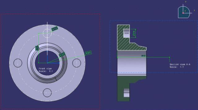
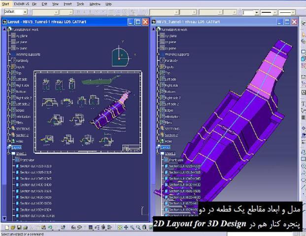
محیط 2D Layout for 3D Design نرم افزار کتیا، تركيبي از دو محیط Part Design و Generative Drafting است. پس از ورود به محیط 2D Layout for 3D Design دو پنجره در كنار يكديگر قرار مي گيرند كه يكي اختصاص به طراحي سه بعدي قطعه و ديگري به استخراج همزمان نقشه هاي دوبعدي آن اختصاص دارد. درخت طراحي واقع در اين دو پنجره نيز مركب است يعني هر دو آنها اطلاعات پنجره ديگر را در بر مي گيرد. اطلاعات اين دو پنجره با نام يك فايل و با پسوند مشابه فايل هاي Part Design ثبت مي شود. از ديگر توانايي هاي محیط 2D Layout for 3D Design استخراج مدل سه بعدي قطعه با تركيب نماهاي دوبعدي آن مي باشد. در واقع در اين محيط كاري مراحل طراحي از محيط كاري نقشه دوبعدي به سمت محيط كاري طراحي قطعه سه بعدي انجام مي شود...
| مجموعه آموزشهای محیط Shape Design & Styling نرم افزار CATIA |
| مجموعه آموزشهای محیط Mold Tooling Design نرم افزار CATIA |
| مجموعه آموزشهای محیط Sheet Metal Design نرم افزار CATIA |
راهنمای استخراج مدل سه بعدي قطعه با تركيب نماهاي دوبعدي در محیط 2D Layout for 3D Design نرم افزار CATIA، یکی از راهنماهای مفید و کاربردی در زمینه نحوه استخراج مدل سه بعدي قطعه با تركيب نماهاي دوبعدي آن در نرم افزار پیشرفته کتیا می باشد. این راهنما (help) مشتمل بر 979 صفحه، به زبان انگلیسی خیلی روان، تایپ شده، به همراه تصاویر رنگی، با فرمت PDF، توسط شرکت Dassault Systems به ترتیب زیر گردآوری شده است:
Getting Started
- Entering the 2D Layout for 3D Design Workbench
- Starting the Preliminary Design of a Part
- Completing the Preliminary Design in Another View
- Creating the 3D Part
User Tasks
- Layout Tools
- Copying, Cutting, Pasting and Deleting
- Layout Creation and Edition
- Creating a Layout
- Opening a Layout
- Navigating Between Windows
- Layout Sheets
- Editing a Sheet and/or its Background
- Modifying a Sheet
- Adding a New Sheet to a Layout
- Setting a Sheet as Current
- View Creation
- Before You Begin Creating Views
- Creating a Projection View
- Creating a Section/Auxiliary View
- Creating a Section From Two Planes
- Creating a View From Another Element
- View Management
- Using the Cutting Plane
- Using the Clipping Frame
- Using the Back-Clipping Plane
- Managing the Layout View Background
- 2D Geometry
- Creating Profiles
- Creating Rectangles
- Creating Oriented Rectangles
- Creating Parallelograms
- Creating Elongated Holes
- Creating Cylindrical Elongated Holes
- Creating Keyhole profiles
- Creating Hexagons
- Creating Centered Rectangles
- Creating Centered Parallelograms
- Creating Circles
- Creating Three Points Circles
- Creating Circles Using Coordinates
- Creating Tri-Tangent Circles
- Creating Three Points Arcs
- Creating Three Points Arcs Using Limits
- Creating Arcs
- Creating Splines
- Connecting Curves with a Spline
- Creating Ellipses
- Creating Parabola by Focus
- Creating Hyperbola by Focus
- Creating Conic Curves
- Creating Lines
- Creating an Infinite Line
- Creating a Bi-Tangent Line
- Creating a Bisecting Line
- Creating a Line Normal to a Curve
- Creating Points
- Creating Points Using Coordinates
- Creating Equidistant Points
- Creating Points Using Intersection
- Creating Points Using Projection
- 2D Geometry Modification
- Modifying Element Coordinates
- Creating Corners
- Creating Chamfers
- Trimming Elements
- Breaking Elements
- Breaking & Trimming
- Closing Elements
- Complementing an Arc
- Creating Mirrored Elements
- Moving Elements by Symmetry
- Translating Elements
- Rotating Elements
- Scaling Elements
- Offsetting Elements
- 2D Components
- Before You Begin With 2D Components
- Creating a 2D Component Reference
- Instantiating a 2D Component
- Editing a 2D Component Instance
- Exploding a 2D Component Instance
- Instantiating a 2D Component from a Catalog
- Exposing a 2D Component from a Catalog
- Dimensioning
- Dimensioning in a 2D Layout for 3D Design Context
- Dimensions and Tolerances
- Before You Begin
- Creating Dimensions
- Creating Half-Dimensions
- Creating Explicit Dimensions
- Creating/Modifying Angle Dimensions
- Creating Fillet Radius Dimensions
- Creating Chamfer Dimensions
- Creating Thread Dimensions
- Creating/Modifying Coordinate Dimensions
- Creating/Modifying Radius Curvature Dimensions
- Creating Overall Curve Dimensions
- Creating Curvilinear Length Dimensions
- Creating Partial Curvilinear Length Dimensions
- Creating Dimensions along a Reference Direction
- Creating Dimensions between Intersection Points
- Creating Dimensions between an Element and a View Axis
- Creating Driving Dimensions
- Modifying the Dimension Type
- Re-routing Dimensions
- Interrupting Extension Lines
- Modifying the Dimension Line Location
- Modifying the Dimension Value Text Position
- Specifying the Dimension Value Position
- Adding Text Before/After the Dimension Value
- Modifying the Dimensions Overrun/Blanking
- Scaling a Dimension
- Lining up Dimensions (Free Space)
- Lining up Dimensions (Reference)
- Creating a Datum Feature
- Modifying a Datum Feature
- Creating a Geometrical Tolerance
- Modifying Geometrical Tolerances
- Copying Geometrical Tolerances
- Dimension Systems
- Before You Begin
- Creating Chained Dimension Systems
- Creating Cumulated Dimension Systems
- Creating Stacked Dimension Systems
- Modifying a Dimension System
- Lining Up Dimension Systems
- Constraints
- Creating Quick Constraints
- Fixing Elements Together
- Creating Constraints via a Dialog Box
- Creating Contact Constraints
- Creating Constraints via SmartPick
- Annotations
- Creating Annotations in a 2D Layout for 3D Design Context
- Before You Begin
- Creating a Free Text
- Creating an Associated Text
- Making an Existing Annotation Associative
- Creating a Text With a Leader
- Adding a Leader to an Existing Annotation
- Handling Annotation Leaders
- Adding Frames or Sub-Frames
- Copying Graphic Properties
- Creating a Datum Target
- Modifying a Datum Target
- Creating a Balloon
- Modifying a Balloon
- Creating a Roughness Symbol
- Creating a Welding Symbol
- Modifying Annotation Positioning
- Creating/Modifying a Table
- Finding and Replacing Text
- Performing an Advanced Search
- Querying Annotation Links
- Adding Attribute Links to Text
- Dress-up
- Creating Dress-up in a 2D Layout for 3D Design Context
- Creating Center Lines - No Reference
- Creating Center Lines - Reference
- Modifying Center Lines or Axis Lines
- Creating Threads - No Reference
- Creating Threads - Reference
- Creating Axis Lines
- Creating Axis Lines and Center Lines
- Creating an Area Fill
- Creating Arrows
- 3D Outputs
- Creating a 3D Profile
- Creating a 3D Plane
- Use-Edges
- Before You Begin With Use-Edges
- Projecting 3D Elements onto the View Plane
- Intersecting 3D Elements with the View Plane
- Projecting 3D Silhouette Edges
- Integration with the Drafting Workbench
- Exporting a Drawing View to a Layout
- Creating Drawings and Drawing Views from a Layout
- Creating View Filters
- Printing a Layout
- Properties
- Editing Sheet Properties
- Editing View Properties
- Editing 2D Geometry Feature Properties
- Editing 2D Element Graphic Properties
- Editing Pattern Properties
- Editing Annotation Font Properties
- Editing Text Properties
- Editing Picture Properties
- Editing Dimension Text Properties
- Editing Dimension Font Properties
- Editing Dimension Value Properties
- Editing Dimension Tolerance Properties
- Editing Dimension Extension Line Properties
- Editing Dimension Line Properties
- Editing Dimension System Properties
- Editing 2D Component Instance Properties
Workbench Description
- 2D Layout for 3D Design Menu Bar
- 2D Layout for 3D Design Toolbars
- Layout
- Constraint
- 3D Geometry
- Tools
- Visualization
- Tools Palette
- Geometry Creation
- Geometry Modification
- Annotations
- Dress-Up
- Dimensioning
- Dimension Properties
- Text Properties
- Graphic Properties
- Style
Customizing
- Customizing Settings
- View Creation
- General
- Layout
- View
- Geometry
- Dimension
- Manipulators
- Annotation and Dress-Up
- Administration
- Customizing Toolbars
Administration Tasks
- Before You Begin
- Administering Standards and Generative View Styles
- Upgrading Standard Files from Previous Releases
- Setting Standard Parameters and Styles
- Before You Begin
- Setting Standard Parameters
- About Standard Parameters
- General
- Dress-Up
- Dimensions
- Tolerance Formats
- Value Formats
- Pre-defined Formats for Tolerance and Dimension Values
- Annotations
- FramesViews
- Line Thicknesses
- Pre-defined Styles DefinitionPatterns
- Line Types
- Sheet Formats
- Layout Views Customization
- Setting Standard Styles
- About Styles
- Geometry Styles
- Annotation Styles
- Dimension Styles
- Dress-up and Dress-up Symbols StylesView Callout Styles
- Sheet Styles
- Dimension System Styles
- Glossary
- Index
توجه: کاربران نگران زبان انگلیسی کتاب نباشند. حتی کاربرانی که سر انگشتی زبان انگلیسی یاد دارند قادر خواهند بود از این کتاب بهره کافی را ببرند. لازم به ذکر است که آموزش استخراج مدل سه بعدي قطعه با تركيب نماهاي دوبعدي در محیط 2D Layout for 3D Design نرم افزار CATIA به صورت پله پله (Step to Step) همراه با تصاویر واضح و رنگی می باشد.
جهت دانلود رایگان راهنمای استخراج مدل سه بعدي قطعه با تركيب نماهاي دوبعدي در محیط 2D Layout for 3D Design نرم افزار CATIA بر لینک زیر کلیک نمایید:

اگر به فراگیری مباحث مشابه مطلب بالا علاقهمند هستید، آموزشهایی که در ادامه آمدهاند نیز به شما پیشنهاد میشوند:
دیدگاه خود را بنویسید